
SHAFT
Summary of this specification
This specification covers the design requirements, geotechnical investigation program at shaft for ground freezing and installation of ground freezing system. It is a combined performance and method approach specification.
This document is intended to be generic specification for installation of ground freezing system at shaft. This can be used as a guideline to design requirements, geotechnical investigations and QA/QC plan.
Guideline Specification for Installation of Ground Freezing System at Shaft Location.
Design Requirements
- Analyze subsurface conditions at shaft site to evaluate conditions affecting ground freezing design and construction.
- The Geotechnical Data Report (GDR) and Soil and Groundwater Environmental Investigation Report provide information on the subsurface conditions at each shaft site, but additional environmental and geotechnical investigations may be needed to determine the actual site conditions.
- Follow the Geotechnical Baseline Report for baselines.
- Before starting work, locate and identify all existing underground utilities or any other object able to affect the drilling activity and the freezing activity.
- Evaluate provided geotechnical information and if necessary develop and perform a Supplemental Geotechnical Investigation Program at each shaft. Investigation at each shaft shall include the following work, as a minimum
- Preparation of the DEP EHS (Department of Environmental Protection – Environmental Health and Safety) Drilling and Boring Checklist.
- Drill one (1) mud-rotary boring in accordance with ASTM D5783 to a specified depth. Obtain a minimum of three (3) undisturbed soil samples (minimum recovery of 20 inches) in each clay soil stratum to perform frozen soil testing as required by the Ground Freeze Engineer of Record (EOR).
- Drill four (4) sonic core borings in accordance with ASTM D6914 with continuous sampling to install one (1) center observation well penetrating to bedrock inside each shaft and three (3) standpipe piezometers screened in the glacial sands and gravels and configured in a triangular arrangement outside the frozen zone. Piezometer borings shall penetrate through the full depth of glacial sand and gravel and have piezometer intakes sealed in the most permeable glacial soils indicated by sampling. Install any other piezometers the Ground Freeze EOR finds necessary to establish the rate of groundwater flow in the most permeable soils. If the piezometer system is not able to provide information about the water flow, other systems have to be implemented.
- Obtain water quality samples from each piezometer and test for salinity and priority pollutants. Test soil samples in each soil stratum for salinity in accordance with ASTM D4542.
- Perform frozen ground lab testing on undisturbed samples including: (1) strength testing at -10 degrees C and at -15 degrees C in each clay soil stratum in accordance with ASTM D7300, (2) creep testing at -10 degrees C and at -15 degrees C in each clay soil stratum in accordance with ASTM D5520 and (3) volumetric expansion testing at -10 degrees C in each clay and silt soil stratum. Creep tests at each temperature shall be performed at two stress levels equivalent to two thirds and the maximum of the expected range of stress levels estimated to occur in the frozen structures during and following excavation. The Engineer conducts frozen ground tests on samples obtained in the borings presented in the GDR.
- Provide inspection of all borings by a qualified geotechnical engineer under the direct supervision of the Ground Freeze EOR. Notify Engineer in advance of borings to allow access for observation of work.
- Submit logs of all borings upon boring completion and a report summarizing the results of the Supplemental Geotechnical Investigation following completion of testing for review and approval of the Engineer.
- Design frozen ground zone at each shaft to provide complete groundwater isolation (cutoff) through overburden soils and top of rock and adequate support of the ground and adjacent structures and utilities using subsurface data provided. The frozen ground shall have a maximum hydraulic conductivity of 1x10⁻⁶ centimeters per second. If low permeability bottom layer is not present, an additional intervention has to be designed, in order to close the bottom part of the shaft.
- Thermal computations shall determine whether additional freeze maintenance effort is required around the rock interface. Should calculations indicate additional freeze maintenance efforts are required, provide a freeze maintenance design specific to the connection. All Freeze Pipes shall extend through all weathered rock and a minimum of 15 feet into Sound or Competent Rock.
- Perform structural computations using Finite Element (FE) analysis that models both stability and deformations for complex soil geometry under static (gravity) loading to determine required dimensions of the frozen zone under maximum anticipated earth and groundwater loads and demonstrate structural adequacy of the Freeze System. The structural computations shall include surcharge earth pressures from adjacent structures, construction equipment and stockpiling of materials as needed as part of the construction plan. The geometry in the model shall be based on the results of the thermal analysis. The minimum short-term strength factor of safety shall be 2.0.
Structural Design shall also include:
a. A reinforced concrete collar extending at least two feet above the surrounding ground surface and extending up to adequate depth with the inside edge at the Excavation Line through which the Freeze Pipes will pass. Collar design must provide the following, as a minimum:
1) Support surficial soils to provide stable work platform around shaft perimeter for all equipment and personnel during shaft excavation.
2) Prevent possible sheet flow or surface water infiltration that could flow into the excavation and cause melting of the frozen cylinder.
3) Provide support for unsaturated soils above groundwater table as necessary, where in groundwater table is deep and possibly ground freezing of unsaturated soils will not be effective.
b. A Temporary Liner applied to the face of frozen ground as excavation proceeds. Temporary Liner design must provide the following, as a minimum:
1) Adequate thermal insulation near the ground surface to assure that the frozen zone is unaffected by warming from the ground surface (coke bottle effect).
2) Adequate temporary support of the frozen ground and thermal insulation at depth to protect the excavated face from warming, control spalling, prevent ice buildup on the face of the excavation walls, and limit creep.
3) Limit creep of the frozen soil over the potential duration of construction prior to the final liner reaching design strength without overstressing Temporary Liner or impacting minimum dimensions of permanent shaft liner. The frozen ground and Temporary Liner shall limit creep strains in the Temporary Liner to no more than 2% radial strain or as otherwise required by the Temporary Liner design.
4) Adequate substrate for installation of waterproofing membrane system in accordance with all requirements. The substrate may be installed as part of the initial Temporary Liner or ahead of placement of final lining.
- Design and install an automated data acquisition and storage system that monitors the Freeze System including instrumentation and monitoring equipment to:
- Determine outgoing and incoming coolant temperature and pressure.
- Detect if a leak is present in the coolant distribution and return system.
- Transmit/upload collected data to the automatic monitoring and data dissemination system.
- Design a ground freezing deformation and temperature instrumentation system to monitor the freeze and thaw extended limits of the Freeze Zone. The ground freezing instrumentation system shall verify the dimensions (width, length, depth) and continuity of the frozen ground zone. The ground freezing instrumentation system shall:
- Determine the temperature of the frozen ground zone and verify the dimensions of the frozen zone for each location and include, at a minimum, four TMBs installed around the Site and within each soil layer, with an accuracy of ± 0.5 degrees C. Three TMBs shall be located where Freeze Pipes are found, through survey, to be most widely spaced to the extent possible. Locate the fourth TMB adjacent to the closest utility to monitor ground temperatures away from freezing front.
- Monitor creep of the frozen soil and inward movement of the frozen ground with depth using Convergence Gage Arrays (CGAs) installed on the shaft sidewalls. CGAs should be installed at approximately 40-ft (min) vertical spacing in sand and gravel layers and 20-ft (min) spacing in clay and silt layers. Each CGA should include optical targets (prisms) and at least five anchorage points installed around the perimeter of the shaft at the same elevation. Use optical survey of prisms as primary method for monitoring shaft convergence. Perform periodic manual survey as secondary method to confirm optical survey results using steel tape and a portable convergence gage to measure the change in horizontal distance between anchorage points at each gage elevation.
- Monitor groundwater levels and shaft inflow during ground freezing operation. At a minimum the groundwater shall be monitored in the three (3) standpipe piezometers and one (1) center observation well-constructed as part of the supplemental investigation. Groundwater observations shall be used to confirm Closure of the ground freezing system and confirm that leaks are not occurring.
- Monitor movement of potential structures and utilities that could be impacted by the ground freezing system.
- If a flexible Temporary Liner is used in design, additional methods of measuring stress and monitoring Temporary Liner movement shall be designed and implemented.
- Transmit/upload collected data to the automatic monitoring and data dissemination system.
- Protect all existing structures and active buried utilities from potential adverse impacts of ground freezing, such as heave or thaw settlement. Pre or post-treatment intervention can be considered.
- Develop criteria for all additional loading and unbalanced loading conditions that will be placed upon the Temporary Liner, collar, underground structures, and utilities due to freezing and thawing of the ground. These criteria should be coordinated with and approved by the EOR of the final structures.
- Coordinate all work to avoid interference with operations of existing facilities.
Implementation
A. Ground Freezing System Installation
- Install freezing system in accordance with approved shop drawings.
- Locate all existing utilities prior to Freeze Pipe installation. Conflicting utilities shall be relocated, or pipe locations adjusted accordingly to prevent damage due to Freeze Pipe installation as per Contract requirements.
- Provide drilling equipment of adequate size, power, and torque to successfully install Freeze Pipes into bedrock through a soil profile known to include significant obstructions including cobbles, boulders and remnant foundations as detailed in the GDR and GBR.
- a. Drill through obstructions and/or install additional Freeze Pipes as necessary to obtain a consistent frozen mass of the minimum dimension as determined by the analysis of the Ground Freeze EOR.
- b. Maintain boring logs for each Freeze Pipe that shall include soil stratification, depth and thickness of obstructions encountered, time required to drill, advancement rates and any record of drilling fluid loss.
- c. Provide standby drill rig available within one hour of each shaft site to meet any contingency issues once freezing or excavation proceeds.
- Dispose of all drill cuttings and drilling fluids in accordance with applicable Federal, State and local regulations, law and ordinances.
- Take appropriate measures to avoid spreading the pollutants when drilling through contaminated soil.
- Perform welding of all pipe joints and end caps by a certified welder.
- Perform verticality survey of each Freeze Pipe following installation using a calibrated gyroscopic device or other devices to establish deviations from planned location.
- Pressure test all coolant distribution system connections for leak detection, and all leaks discovered during this testing shall be repaired before the Coolant is introduced. Hold the pressure for a minimum of 15 minutes.
- Repair, replace or supplement with additional Freeze Pipes any Freeze Pipe failing to meet the pressure test or specified deviation tolerances.
B. Freezing Plant Performance Requirements
- Always operate the freezing plant appropriately in accordance with current labor and safety requirements and as required to meet the Ground Freezing performance objectives.
- Provide sufficient freeze units to freeze and maintain the frozen ground at each shaft. A standby freeze unit shall be provided and maintained as a backup in the event a primary unit malfunctions during excavation.
C. Freezing System Operation
- Evaluate the performance of the ground freezing system daily from the start of excavation until the end of the thawing phase.
- a. Locate anomalies in Coolant temperature splits and areas drawing greater energy.
- b. Modify system to close windows or openings, including extending the freeze time, installing additional Freeze Pipes, or performing ground improvement such as grouting.
- Apply Temporary Liner to the exposed frozen soil as necessary to preserve integrity of the frozen ground during shaft excavation.
- Maintain the integrity of frozen ground by whatever means required.
- Place Temporary Liner in accordance with approved shop drawings.
- a. Maximum height of exposed frozen ground shall not exceed 10 feet before placement of the Temporary Liner.
- b. If spray foam insulation is used as part of the Temporary Liner, reinforcement shall be applied against the exposed surface of frozen ground before the application of spray foam insulation.
- c. Temporary Liner shall be applied within 12 hours of exposing the frozen ground at the Excavation Line
- d. If shotcrete is installed as part of the Temporary Liner, the shotcrete shall be installed in accordance with the requirements.
D. Excavation
- Perform excavation within the limits of the frozen wall in accordance with the requirements.
- Provide stable and safe excavation within frozen wall by whatever means required that shall allow construction of the shaft.
- Frozen ground extending within the excavation neat line shall be excavated by mechanical means. Boulders and cobbles projecting within the excavation limits from the frozen wall shall be excavated using mechanical rock splitters or other approved methods. Blasting of frozen ground is not permitted and the vibrations have to be limited
- Do not stockpile excavated material against or within 4-feet of exposed frozen ground surface.
E. Structure Protection
Use whatever means necessary to limit ground movements and settlements and damage to adjacent and nearby structures and utilities, including but not limited to installation of warming pipes to regulate the limits of freezing, installation of ground support systems, and grouting.
Field Testing / Quality Control
- All Freeze Pipes shall be surveyed to determine variation from planned position with depth, using gyroscopic devices or other approved methods. Method of survey shall be submitted for review by the Engineer.
- Temperature Monitoring Boreholes
- Install TMB’s at locations proposed by the subcontractor and reviewed by the Engineer.
- Install TMB's subsequent to completion of the Freeze Pipe installation and verticality survey and prior to the start of ground freezing.
- Install temperature probes conforming to the material requirements of this Item and in accordance with the manufacturer's requirements.
- Install temperature probes in TMB's at five (5) feet depth intervals as a minimum, subject to modification by the freeze wall subcontractor.
General Requirements for Monitoring
- Provide a monitoring system capable of thermo-profiling to guide freezing operations to verify that the ground is frozen to the dimensions and temperature indicated in the design.
- Correlate temperature monitoring with the results of the heave and settlement monitoring. All temperature monitoring shall be planned by the Contractor and the Contractor shall install and operate the system and read and interpret the data. Access to the freeze tubes for temperature monitoring shall be facilitated.
- At a minimum the monitoring system shall include:
- Temperature monitoring boreholes (TMB's) at each ground freezing shaft (quantity to be determined by Contractor's design).
- Temperature monitoring of brine supply header, return header, and each primary circuit return.
- Temperature monitoring system capable of thermo-profiling to guide freeze operations to verify the ground freeze with computer plotting of real time temperature measurements and real time temperature splits of brine flowing in and out of the ground. There needs to be a clear correlation between the actual sensor data and the location of the freezing in the ground to ensure accurate monitoring and assessment monitoring and assessment of the ground freezing process.
- Brine flow monitoring including loss of circulation and/or loss of Coolant
- Monitoring of active freeze units including temperature, flow rate and on/off status.
- Deformation monitoring points as specified in Section 31 09 10 - Geotechnical and Structural Monitoring.
- Convergence Gage Arrays to monitor horizontal displacements of the excavation face.
- Water levels in piezometers and center observation well.
- Quantity of water inflow through observation/pressure relief wells at each shaft site.
- Reports for monitoring shall be provided in a format approved by the Engineer.
- Monitoring Frequency
- Obtain at least two (2) weeks of daily initial readings for each instrument prior to the start of the ground freeze.
- If grout is used, baseline readings should not be attempted until grout has set (minimum 72 hours, or as recommended by the instrument manufacturer).
- Monitor each instrument daily from the start of ground freezing until completion of the interior concrete wall or until destroyed by the excavation.
- Monitor Convergence Arrays weekly with optical survey and monthly with extensometers to confirm optical survey results.
- Monitor each instrument weekly for two months after the ground freezing system is turned off.
- Report all monitoring results to the Engineer within 24 hours of completion of the monitoring.
- Reporting Format
- Provide daily reports for temperature sensors in TMB's to the Engineer. The report shall consist of a plot of temperature versus elevation for each TMB.
TUNNEL
This specification guides the contractor to use ground freezing for providing temporary excavation support or ground stabilization for the tunnel. This specification contains sections like design requirements, QA/QC requirements, Adit excavation and support, and Geotechnical Instrumentation and Monitoring.
Design Criteria
- The Design-Builder shall develop and perform a Supplementary Geotechnical Investigation Program. Include a minimum of one (1) boring at each location where ground freezing is proposed.
- Obtain a minimum of three (3) undisturbed soil samples of each plastic soil type extracted to perform the frozen soil tests as required by the Design-Builder’s ground freeze EOR. As a minimum, frozen ground lab testing shall include strength testing at -10 degrees C and at -15 degrees C. In addition, creep deformation tests shall be performed at two stress levels that are at two thirds and the maximum of expected range of maximum stress levels estimated to occur in the frozen structures during and following excavation at both frozen ground temperatures listed above.
- The frozen ground shall have a maximum hydraulic Conductivity of 1 x 10⁻⁶ centimeters per second.
- The Design-Builder shall demonstrate adequacy of the freeze system with a Finite Element (FE) 2D analysis that models thermal changes in the ground due to heat extraction by freeze pipes and phase changes of water into ice and vice versa.
- The Design-Builder shall design and install an automated data acquisition and storage system that includes instrumentation and monitoring equipment to:
- Verify the dimensions (width, length, depth) and continuity of frozen ground zone.
- Determine the temperature of the frozen ground zone for each location and include, at a minimum, five to six temperature monitoring pipes within each soil layer, with an accuracy of ± 0.5 degrees C.
- Determine outgoing and incoming coolant temperature and pressure.
- Detects if a leak is present in the coolant distribution and return system.
- Transmits, in real-time, the collected data to the automatic monitoring and data dissemination system.
- The Design-Builder shall design and layout ground deformation and temperature instrumentation to monitor the freeze and thaw extended limits of the freeze zone. For the purpose of instrumentation layout, use an additional 100% of the initially planned development time to determine the extended limits of the freeze zone.
- This extended limit of freeze shall be used to establish the limits of the monitoring system (ground deformation and temperature) and to identify potentially impacted structures and utilities and complete analyses for those structures and utilities.
- The Design-Builder shall design the freeze system to accommodate alternating coolant circulation, such that coolant can flow between alternating freeze pipes during maintenance freezing or other means such as reduced pumping rate or using warmer coolant.
I. The Design-Builder shall design the freeze system to include, at a minimum the following:
- A coolant balance tank insulated flow and return mains, and appropriate pumps, air release valves, temperature, and flow measurement instruments.
- Each freeze pipe shall have a control isolating valve and an air bleed valve.
- The coolant circulation system shall have an automatic shut-off control when there is a sudden drop in pressure to limit loss if a leak develops.
- Each series of freeze pipes shall be arranged in a loop between the supply and return manifolds and shall contain provision for coolant temperature measurements for both supply and return.
- The Design-Builder freeze design shall demonstrate whether additional freeze maintenance effort is required around connections where TBM or other excavation methods have removed or disrupted freeze development or maintenance pipes. Should calculations indicate additional freeze maintenance efforts are required, provide a freeze maintenance design specific to the connection.
Execution
General
- Prior to start of work, calibrate all temperature monitoring devices. Maintain files of calibration test reports of all temperature monitoring devices.
- Pressure test the manifold assembly to two times the anticipated working pressure. Maintain results of pressure testing of all freeze system components on site.
- Prior to start of ground freeze system installation and operation, install the instrumentation as indicated in the ground freezing design EOR’s design submittal and Geotechnical Instrumentation and Monitoring. Install temperature measurement devices and monitor ground temperatures a minimum of two weeks before any freezing operation.
- The Design-Builder shall be fully responsible to furnish, install, monitor, maintain, and remove instrumentation. Provide access to instrument locations and maintain instruments from damage.
- In the event that monitoring indicates a breach in the freeze zone, excessive settlement or excessive heave (approaching established Maximum Limits), the Design-builder may be required to modify the means and methods to prevent additional movements. The Design-Builder shall be responsible for making a prompt evaluation of the freeze zone and taking immediate steps to prevent damage or excessive movements.
- Protect existing structures and utilities within or adjacent to the Work areas in accordance with the requirements of authorities having jurisdiction. The Design-Builder is responsible for any damage caused by their operations and shall restore structures or utilities to equal or better operation at no additional cost to the Owner.
- The Design-Builder shall be responsible for coordinating the Work with other trades and third parties affected by the Work of this section to ensure the steady progress of all the Work under the Contract.
Installation and Application
- Install the freeze and temperature measuring pipes and ancillary equipment in accordance with the reviewed submittals. Survey pipe verticality, horizontally, and install additional freeze pipes as necessary to achieve required pipe spacing.
- Leak test all installed freeze and temperature measuring pipes as indicated herein. Repair or replace any pipes failing leak test.
- Determine baseline temperature readings at least seven days prior to activation of freeze system.
- Evaluate the performance of the ground freezing system daily from the start of excavation until the final liner or permanent support walls have been constructed.
- Locate anomalies in coolant temperature splits and areas drawing greater energy.
- Modify system to close windows or openings, including installing additional freeze pipes or ground improvement such as grouting.
- Monitor the freeze system throughout the depth of the frozen zone at locations where the relative spacing of the freeze pipes is greatest as indicated herein.
- Adjust the system to satisfy the design criteria.
- Notify the Owner of deviation from submitted schedule within 24 hours of readings.
- Implement contingencies as required and notify the Owner.
- Continue to monitor until the freeze wall is fully thawed.
F. Decommissioning
1. File notice of intent to decommission with (Department of Energy and Environment) DOEE and submit a copy to the Owner.
2. Purge all pipelines and tanks of coolant and evacuate freeze pipes with fresh water.
3. Dispose of coolant in an approved manner. Remove all equipment from the site.
Field Quality Control
- Perform quality control monitoring during installation of the freeze and temperature pipes, and all other components of the freeze system.
- Perform down hole survey of each pipe, utilizing gyroscope, to determine the three-dimensional location with length. Document deviation from design location and spacing between the pipes vs. length.
- Perform first pressure test of the freeze and temperature pipes following installation prior to further connection to the freeze system.
- Test each outer pipe for leak detection by filling with water and pressurizing to a minimum pressure of two times the design operating pressure of the system. Hold the pressure for a minimum of 15 minutes.
- Daily Monitoring
- Prepare a daily report which indicates performance of the freeze plant, coolant flow volume, and temperature in circulation.
- Perform surveillance and maintenance of all freezing equipment at least twice a week. Inspection methods to be tailored to site circumstances and shall include, as a minimum, a check for valve operation and a visual inspection of all lines for coolant fluid leakage.
- After the permanent construction is completed, continue to monitor the ground temperatures and geotechnical instrumentation once per month, if there is no indication of exceedance, until the ground is fully thawed.
Table 1. Specification identification table
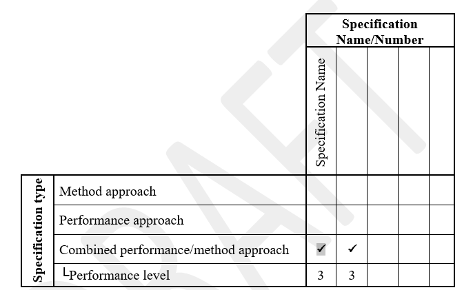
Performance level:
1 - Actual performance measured after construction (e.g., settlement at a specific time) and warranty provisions might be included
2 - Performance-related properties measured at end of construction (e.g., CPT, vane shear, etc.)
3 - Design properties measured during construction (e.g., modulus measured for each lift)
4 - Design-related properties measured during construction (e.g., density and water content measured for each lift)
References
Specifications for Shaft and Tunnel ground freezing were obtained from Keller North America contract dements