
Preferred Design Procedure
The Federal Highway Administration (FHWA) has two documents for this technology that contain design guidance information
| Publication Title | Publication Year | Publication Number | Available for Download |
|---|---|---|---|
| Design and Construction of Stone Columns — Volume I (Barksdale and Bachus 1983a) |
|
|
|
| Ground Modification Methods — Volume I (Schaefer et al. 2016a) |
|
|
|
- http://www.fhwa.dot.gov/engineering/geotech/library_listing.cfm
- https://www.fhwa.dot.gov/engineering/geotech/pubs/nhi16027.pdf
In addition, the Highway Innovative Technology Evaluation Center (HITEC) published a technical evaluation report on Geopier Rammed Aggregate Piers. This report, referenced below, contains detailed design guidance and is available for purchase through the ASCE bookstore at http://www.asce.org.
Collin, J. G., (2007) “Evaluation of Rammed Aggregate Piers by Geopier Foundation Company Final Report” Technical Evaluation Report prepared by the Highway Innovative Technology Evaluation Center, ASCE, September 2007.
If aggregate columns are to be used for embankment support, then the Design Guidance for Column-Supported Embankments should also be consulted for recommended design procedures for the arching/load transfer mechanism from the embankment to the columns.
Typical inputs and outputs associated with analysis and design are listed in Table 1. A final design will usually consist of the number, diameter, length, spacing, and geometrical arrangement of aggregate columns and the required properties of the compacted stone after installation.
Table 1. Typical inputs and outputs for design and analysis procedures.
Performance Criteria/Indicators
FSmin for bearing capacity
FSmin for slope stability
FSmin for liquefaction
Allowable settlement
Allowable deformations
Subsurface Conditions
Undrained Shear Strength, su
Effective Internal friction angle, ϕ'
Unit weight
Young's modulus
Poisson's ratio
Compression index/Compression ratio
Coefficient of consolidation
Void Ratio
SPT N-Values
CPT Tip Resistance and Sleeve Friction
Shear Wave Velocity
Permeability/Hydraulic Conductivity
Delineation of Stratigraphy
Modulus of subgrade reaction (k) for soft soils
Gradation
Loading Conditions
Embankment loading
Structural load
Uplift load
Stress concentration ratio
Earthquake acceleration and duration
Material Characteristics
Final (N1)60 of treated soil
Final (qc)1 of treated soil
Final (vs)1 of treated soil
Friction angle of stone
In-place density of stone
Permeability of stone
Column stiffness modulus
Stone gradation
Construction Techniques
Vibro-replacement
Vibro-displacement
Rammed aggregate piers
Geometry
Column spacing
Column diameter
Column length
Column pattern
Treatment area
Replacement ratio
References
Al-Homoud, A.S., and Degen, W.S. (2006). “Marine stone columns to prevent earthquake induced soil liquefaction.” Geotechnical and Geological Engineering, 24, 775-790.
Baez, J.I. and Martin, G. (1993), "Advances in the Design of Vibro Systems for the Improvement of Liquefaction Resistance." Proceedings of the Symposium on Ground Improvement, Vancouver, British Columbia.
Barksdale, R.D. and Bachus, R.C. (1983a). Design and Construction of Stone Columns Vol. I. FHWA/RD-83/026.
Barksdale, R.D. and Bachus, R.C. (1983b). Design and Construction of Stone Columns Vol. II. FHWA/RD-83/027.
Collin, J. G., (2007) “Evaluation of Rammed Aggregate Piers by Geopier Foundation Company Final Report” Technical Evaluation Report prepared by the Highway Innovative Technology Evaluation Center, ASCE, September 2007.
Fox, N. S. and Lien, B. H. (2001a). “Geopier® Soil Reinforcement Technology: An Overview.” Proceedings, Asian Institute of Technology Conference. Bangkok, Thailand. November.
Fox, N. S. and Lien, B. H. (2001b). “Geopier® Floating Foundations- A Solution for the Mekong Delta Region, Vietnam.” Proceedings of the International Conference on Management of the Land and Water Resources. Hanoi, Vietnam. October 20-22.
Hall, K., Wissmann, K. J., Caskey, J. M. and FitzPatrick, B. T. (2002). “Soil Reinforcement Used to Arrest Bearing Capacity Failure at a Steel Mill.” Proceedings of the 4th International Conference on Ground Improvement Techniques. Kuala Lumpur, Malaysia. March 26-28.
Han, J. and Ye, S. (2001). “Simplified method for consolidation rate of stone column reinforced foundations.” Journal of Geotechnical and Geoenvironmental Engineering, ASCE, 127(7), 597-603.
Han, J. and Ye, S.L. (2002). “A theoretical solution for consolidation rates of stone column-reinforced foundations accounting for smear and well resistance effects.” The International Journal of Geomechanics, 2(2), 135-151.
Han, K. K., Lien, B. and Fox, N. S. (2002b). “Stabilizing Landslides Using Rammed Aggregate Piers.” 5th Malaysian Road Conference, Kuala Lumpur, Malaysia, October 7-9, 2002.
Han, K. K., Fox, N. S. and Lien, B. (2002c). “Innovated and Alternative Foundation Systems.” 2nd IKRAM International Geotechnical Conference (IGEO-2). Kuala Lumpur, Malaysia. Oct. 28.
Idriss, I.M. and Boulanger, R.W. (2008). Soil Liquefaction During Earthquakes, Earthquake Engineering Research Institute Monograph MNO-12, 235 pp.
Lawton, E. C. (2000). “Performance of Geopier Reinforced Soil Foundations During Simulated Seismic Tests on I-15 Bridge Bents.” Proceedings of Soil Mechanics 2000 and Journal of the Transportation Research Board. Washington, DC 2000.
Lawton, E. C., Fox, N. S. and Handy, R. L. (1994). “Control of Settlement and Uplift of Structures Using Short Aggregate Piers.” Proceedings, IN-SITU Deep Soil Improvements. October 9-13.
Lien, B. H. and Fox, N. S. (2001). “Case Histories of Geopier® Soil Reinforcement for Transportation Applications.” Proceedings, Asian Institute of Technology Conference. Bangkok, Thailand. November.
Majchrzak, M., Lew, M., Sorensen, K., and Farrell, T. (2004). “Settlement of Shallow Foundations Constructed Over Reinforced Soil: Design Estimates vs. Measurements.” Fifth International Conference on Case Histories in Geotechnical Engineering, April 2004.
Minks, A. G., Wissmann, K. J., Caskey, J. M. and Pando, M. A. (2001). “Distribution of Stresses and Settlements Below Floor Slabs Supported by Rammed Aggregate Piers.” Proceedings, 54th Canadian Geotechnical Conference. Calgary, Alberta. September 16-19.
Mitchell, J.K. (1981b). “Soil Improvement: State-of-the-Art”. Session 12, Tenth International Conference on Soil Mechanics and Foundation Engineering, Stockholm, Sweden, June 15-19.
Parra, Jorge R.; Caskey, J. Matthew; Marx, Eric, and Dennis, Norman. (2007). “Stabilization of Failing Slopes Using Rammed Aggregate Pier Reinforcing Elements.” Presented at Geo-Denver 2007. February 2007.
Priebe, H.J.. (1995). “The design of vibro replacement.” Ground Engineering, 28(10), 31-37.
Priebe, H. J. (1998). “Vibro Replacement to prevent earthquake induced liquefaction.” Ground Engineering, September, 30-33.
Schaefer, V.R., Berg, R.R., Collin, J.G., Christopher, B.R., DiMaggio, J.A., Filz, G.M., Bruce, D.A., and Ayala, D. (2016). “Ground Modification Methods,” Federal Highway Administration, Washington, DC, FHWA NHI-16-027 (Vol. I), 386p. https://www.fhwa.dot.gov/engineering/geotech/pubs/nhi16027.pdf
Shenthan, T., Thevanayagam, S., and Martin, G.R. (2006). “Numerical simulation of soil densification using vibro-stone columns,” ASCE, Geotechnical Engineering in the Information Age, Eds. D.J. Degroot, et al.
Suleiman, M. T. and White, D. (2006). “Load transfer in rammed aggregate piers.” International Journal of Geomechanics, 6(6), 389-398.
White, D. and Suleiman, M. (2004). “Design of Short Aggregate Piers to Support Highway Embankments.” Transportation Research Board Annual Meeting, January 2004.
Wissmann, K. J. and Fox, N. S. (2000). “Design and Analysis of Short Aggregate Piers Used to Reinforce Soils for Foundation Support.” Proceedings, Darmstadt Technical University Colloquium. Darmstadt, Germany. March.
Wissmann, K. J. and Minks, A. G. (1999). “Innovative Foundation System Hits a Home Run at Memphis Autozone Park.” Paper presented at the Memphis Area Engineering Society Conference. May.
Wissmann, K. J., FitzPatrick, B. T., White, D. J., Lien, B. H. (2002). “Improving Global Stability and Controlling Settlement with Geopier® Soil Reinforcing Elements.” Proceedings of the 4th International Conference on Ground Improvement Techniques. Kuala Lumpur, Malaysia. March 26-28.
Wissmann, K. J., Fox, N. S. and Martin, J. P. (2000). “Rammed Aggregate Piers Defeat 75-Foot Long Driven Piles.” Proceedings, Performance Confirmation of Constructed Geotechnical Facilities. ASCE Special Publication No. 194. Amherst, MA. April 9-12.
Wissmann, Kord J.; White, David J., and Lawton, Evert. (2007) “Load Test Comparisons for Rammed Aggregate Piers and Pier Groups.” Presented at Geo-Denver 2007. February 2007.
Wong, D.O., FitzPatrick, B.T. and Wissmann, K.J. (2004). “Stabilization of Retaining Walls and Embankments Using Rammed Aggregate PiersTM.” Proceedings of Geo-Trans 2004. Los Angeles, CA. July 27-31.
Youd, T.L., Idriss, I.M., Andrus, R.D., Arango. I., Castro, G., Christian, J.T., Dobry, R., Finn, W.D.L., Harder, L.F., Hynes, M.E., Ishihara, K., Koester, J.P., Liao, S.S.C., Marcuson, W.F., Martin, G.R., Mitchell, J.K., Moriwaki, Y., Power, M.S., Robertson, P.K., Seed, R.B., and Stokoe, K.H. (2001). “Liquefaction Resistance of Soils: Summary Report from the 1996 NCEER and 1998 NCEER/NSF Workshops on Evaluation of Liquefaction Resistance of Soils”, J. of Geotechnical and Geoenvironmental Engineering, ASCE, Vol. 127, No. 10, pp. 817 – 833. http://ascelibrary.org/doi/abs/10.1061/%28ASCE%291090-0241%282001%29127%3A10%28817%29
Recommended Design/Analysis Approaches
There is no single design procedure that applies to all applications of aggregate columns. Design guidance is provided herein for the most important applications.Analysis and design approaches are given below for determination of bearing capacity, uplift capacity, settlement, composite shear strength, and liquefaction potential. One or more of these determinations is needed for each of the usual applications of aggregate columns.
Aggregate column technology is suitable for support of embankments, support of structures, and improvement of slope stability. Support of embankments and support of structures applications may require an aggregate column design that provides adequate bearing capacity and uplift capacity, limits settlement, and maintains liquefaction potential within specified limits. Slope stability applications may require an aggregate column design that provides a specified minimum shear strength and limits the liquefaction potential. The following design approaches have been developed for each of these considerations. When appropriate, separate approaches for stone columns and rammed aggregate piers are provided.
Bearing Capacity. Approaches for determination of the bearing capacity of a stone column improved soft soil are based on several mechanisms:
- Cavity expansion theory (Barksdale and Bachus 1983a, and Schaefer et al. 2016a).
- General bearing capacity and punching failure (Barksdale and Bachus 1983a).
- Wedge failure method (Barksdale and Bachus 1983a)
- Undrained shear strength method (Mitchell 1981b, Barksdale and Bachus 1983a, and Schaefer et al. 2016a).
- Priebe’s method (Priebe 1995).
- Cavity expansion theory (White and Suleiman 2004, and Wissman et al. 2001b).
- A modified Terzaghi lower bound approach (Collin 2007, Hall et al. 2002, and Wissman et al. 2001b).

Consider a loaded, compacted column analogous to a triaxial shear test. The column fails in shear when:
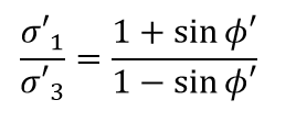
where,
ϕ'= friction angle of stone
By analogy σ'1= σ'v and σ'3=σ'rL
![]()
For ϕ' =35o (conservative), σ'v = 3.7 σ'rL
The value of σ'rL depends on the resistance provided by the surrounding soil as the cylindrical stone column expands radially into it when a vertical load is applied to the top of the column. This condition can be modeled as expansion of a cylindrical cavity in a linear elasto-plastic material.
According to cavity expansion theory for an elasto-plastic material,
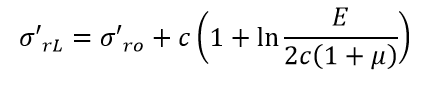
where,
σ'ro= initial lateral pressure and
µ= Poisson's ratio = 0.5 for undrained deformation of saturated clay
E/c ≈100 to 1000 for clays of high to low plasticity (an empirical fact)
Therefore,
A conservative assumption is that σ'rL = σ'ro+ 4c, therefore,
![]()
σ'ro can be expressed in terms of c: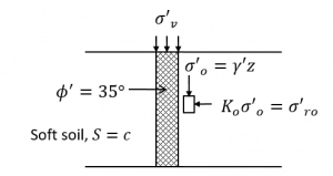
Assume the lateral earth pressure coefficient Ko=0.8 (±), a reasonable value for a column expanding into a clay, and (Su/P)=(c⁄σ'o )≈0.25.
Therefore, σ'o=4c and Ko σ'o=3.2c=σ'ro.
![]()
which is approximately:
σ'v(allow) = 25c/F
where,
F = factor of safety
The above expression gives an allowable load of about 20 to 30 tons for a 1-meter diameter column in soft to medium stiff clay, which agrees well with experience.
Uplift Capacity. If required, rammed aggregate piers can be designed to provide uplift capacity. This is done by including a metal frame in the column during construction that is anchored between the bottom lifts. The foundation can be attached to the frame to provide resistance against uplift. In current practice, stone columns cannot be designed to provide uplift capacity. One approach for estimating the uplift capacity of rammed aggregate piers is based on Lien and Fox (2001) and Wissman and Fox (2000).
The Lien and Fox (2001) procedure includes the following steps:
- The Rankine passive earth pressure coefficient is calculated for the matrix soil and multiplied by the vertical effective stress to determine the horizontal effective stress on the column.
- The unit frictional resistance on the column is calculated based on drained parameters using the following equation:
 where,
fs = unit friction resistance
c’ = drained cohesion intercept of the matrix soil
σ'h = horizontal effective stress on the column
ϕ'm = drained friction angle of the matrix soil - For cohesionless soils, the unit uplift resistance along the column is equal to the unit frictional resistance. For cohesive soil, the unit uplift resistance is equal to the smaller of (1) the unit frictional resistance or (2) the undrained shear strength of the matrix soil.
- Equilibrium method (Mitchell 1981b, and Barksdale and Bachus 1983a).
- Greenwood method (Barksdale and Bachus 1983a).
- Finite element method design charts (Barksdale and Bachus 1983a).
- Priebe’s method (Priebe 1995).
Approaches for estimating settlement magnitude of rammed aggregate pier improved soil are based on two methods:
- Two-layer approach (Collin 2007, Fox and Lien 2001a, Fox and Lien 2001b, Han et al. 2002c, Lawton et al. 1994, Majchrzak et al. 2004, Minks et al. 2001, White and Suleiman 2004, Wissman and Fox 2000, Wissman and Minks 1999, Wissman et al. 2000, Wissman et al. 2002, and Wissman et al. 2007).
- Suleiman and White approach (Suleiman and White 2006).
Settlement Magnitude – Stone Columns. To estimate settlement magnitude of stone column-improved soil, Barksdale and Bachus (1983a) recommend that the equilibrium method be used as an upper bound estimate and their finite element design charts be used as a lower bound and suggest that the best estimate of settlement can generally be taken as the average of these two values. Schaefer et al. (2016a) recommends the same general approach for preliminary settlement estimates with Priebe’s method used to determine the upper bound.
The equilibrium method includes the following steps:
- Estimate a value to be used as the stress concentration factor. The stress concentration factor, ns, is the ratio of vertical steady state stress in the stone column to vertical stress in the matrix soil. Barksdale and Bachus (1983a) provide both theoretically and empirically determined values for the stress concentration factor. They generally recommend values between 2 and 5 but provide additional discussion in Chapter VII.
- Calculate the area replacement ratio for the design. The area replacement ratio, as, is equal to the area of the stone columns divided by the total area.
- Determine the resulting final vertical stress in the matrix soil, σc. This can be determined based on the following equation:
 where,
σ= average final stress over the entire area being considered - Use conventional one-dimensional consolidation theory to estimate the settlement of the stone column improved soil assuming compression under the estimated vertical stress in the matrix soil.
Figures 6 and 7 of Priebe (1995) provide charts for predicting the settlement ratio beneath single and strip footings, respectively. The author does not provide any definition of “single”, but it can be assumed that isolated square or circular footings are considered single footings. The charts predict settlement ratios based on the depth to diameter ratio and the number of stone columns for single footings, and the depth to diameter ratio and number of stone column rows for strip footings. These charts apply only to homogenous soil masses. Even with homogeneous profiles, it is necessary to divide the profile into layers, and then sum the settlements of the individual layers to find the total settlement.
The methods presented here are still rather crude and give a wide range of possible values.
Settlement Magnitude – Rammed Aggregate Piers. The two layer approach is the preferred method for estimating the settlement magnitude of rammed aggregate pier-improved soils. In this method, the reinforced zone is referred to as the upper-zone, and the layer below the reinforced zone is referred to as the lower-zone. The total settlement is the sum of the upper zone settlement and the lower zone settlement.
This method includes the following steps:
- The stress on the top of the rammed aggregate pier is estimated using the following equation:
 where,
qg = stress on top of the column
q = average final stress over the entire area being considered
ns = stress concentration ratio between the rammed aggregate piers and matrix soil; Collin (2007) recommends values between 4 and 45 for rigid footings and values between 5 and 10 for embankments.
Ra = ratio of the cross-sectional area coverage of the rammed aggregate piers to the matrix soil - The settlement of the upper-zone is estimated as the stress on top of the column divided by the column stiffness modulus. According to Collin (2007), stiffness modulus values range from 75 to 360 pci for support of rigid footings. Conservative values are recommended for support of embankments and transportation-related structures.
- The settlement of the lower-zone is estimated using conventional geotechnical approaches. Typically, elastic settlement analyses are used for granular and heavily over-consolidated soils, and consolidation settlement analyses are used for normally-consolidated or lightly over-consolidated cohesive soils.
- Determine the equivalent influence diameter and the diameter ratio, and estimate the stress concentration factor.
- The equivalent influence diameter is equal to the diameter of the circle around an aggregate column having the same area as the column tributary area:de=1.05s for an equilateral triangular pattern
de=1.13s for a square grid patternwhere,de = equivalent influence diameter
s = column center-to-center spacing - The diameter ratio, , is equal to the equivalent influence diameter divided by the column diameter.
- Han and Ye (2002) state that typical values for the stress concentration factor, ns, range from 2 to 5.
- The equivalent influence diameter is equal to the diameter of the circle around an aggregate column having the same area as the column tributary area:de=1.05s for an equilateral triangular pattern
- Calculate the modified coefficient of consolidation due to radial flow and the modified time factor using equation (3) from Han and Ye (2002):
 where,
Trm = modified time factor due to radial consolidation
t = time
crm = modified coefficient of consolidation due to radial flow= cr = coefficient of consolidation due to radial flow
 - Calculate the parameter and the radial degree of consolidation, Ur, using equation (40) from Han and Ye (2002):
and

where,
S = diameter ratio of the smeared zone to the column
= ds/dckr = radial permeability of the undisturbed surrounding soil
ks = radial permeability of the smear zone
kc = permeability of the aggregate column
H = longest drainage distance for vertical flow - Although typically negligible, it may be desirable in some cases to consider the consolidation due to vertical flow. If so, equation (4) from Han and Ye (2002) should be used to determine the modified coefficient of consolidation and modified time factor:
 where,
Tvm = modified time factor due to vertical consolidation
cvm = modified coefficient of consolidation due to vertical flow= cv = coefficient of consolidation due to vertical flow
 - The vertical degree of consolidation, Uz, can then be calculated based on the Terzaghi one-dimensional solution. The overall degree of consolidation, U, is then given by:
Liquefaction Potential. If aggregate columns are to be used in potentially liquefiable soils, there is risk of loss of support and lateral spreading in the event of an earthquake. Approaches for determining liquefaction potential of stone column-improved soil are based on:
- Liquefaction mitigation due to densification (Al-Homoud and Degen 2006, Schaefer et al. 2016a, Shenthan et al 2006, Priebe 1995, and Priebe 1998).
- Liquefaction mitigation due to stress concentration (Baez and Martin 1993).
A simplified general approach for evaluation of liquefaction potential is as follows:
Aggregate column technology may be used at sites with in-situ soils that may be susceptible to liquefaction during earthquakes. Saturated sands, silty sands, sandy silts, and silts are likely to be in this category. When aggregate columns are used for support of embankments and structures, to reduce settlements, or to increase slope stability, it is also necessary to confirm that there will not be a risk of liquefaction or other ground disturbance that could lead to loss of support and lateral spreading. The initial assessment of whether the soil at a site will liquefy in an earthquake is made in terms of whether the in-situ shear strength under cyclic loading, represented as a Cyclic Resistance Ratio (CRR), is less than the cyclic shear stress that will cause liquefaction, termed the Cyclic Stress Ratio (CSR).
Combinations of CSR and strength of the soil layer, usually determined in-situ by means of penetration tests and shear wave velocity[1] measurements, have been found that define the boundary between liquefaction and no liquefaction over a range of peak ground motion accelerations. This boundary has been determined through extensive analyses of case history data from many earthquakes. Standard Penetration Tests (SPT), Cone Penetration Tests (CPT), and Becker Penetration Tests for soils containing gravel and cobbles (BPT) are used to determine the CRR. Values of CRR are defined by the points on the boundary curve that separates liquefaction and no liquefaction zones on a plot of CSR vs. penetration resistance or shear wave velocity corresponding to the measured and corrected in-situ property. An example of such a plot for liquefaction analysis using the SPT is shown in Figure 1.
[1] Owing to the lack of precision and uncertainties associated with shear wave velocity - liquefaction correlations, this method is not considered further herein.
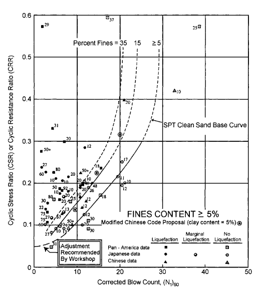
Figure 1. SPT liquefaction chart for magnitude 7.5 earthquakes (Youd et al. 2001).
Thus, if a site underlain by saturated clean sand has a corrected blow count (N1)60 of 10 blows per foot and the anticipated cyclic stress ratio under the design earthquake is 0.25, the soil will liquefy unless the normalized penetration resistance (N1)60 is increased to greater than 22 blows per foot by densification, or the cyclic stress ratio is reduced by transferring some or all of the dynamic shear stress to reinforcing elements. Similar plots are available in terms of normalized CPT tip resistance qc1N. In each case the penetration resistance is normalized to an effective overburden stress of 1 atmosphere.
Although straightforward in concept, the liquefaction potential analysis is complex in application, because (1) the CSR depends on the input motions within the soil layer which, in turn, depend on such factors as earthquake magnitude and intensity, distance from the epicenter, geologic setting, rock conditions, and soil profile characteristics, (2) the CRR depends on such factors as overburden stress, fines content of the soil, and static shear stress, and (3) determination of normalized values of the penetration resistance involves several corrections to the measured values, especially in the case of the SPT.
Information about input ground motions can be obtained from local experience and recorded ground motions near the site, if available, or from seismicity information obtainable from the
- United States Geological Survey Ground Motion Calculator (https://earthquake.usgs.gov/hazards/designmaps/), which can be used to obtain peak rock accelerations for the site
- USGS Earthquakes Hazards Program website (https://earthquake.usgs.gov/hazards/), which provides design ground motions for buildings and bridges; interactive fault maps; scenarios of ground motions and effects of specific hypothetical large earthquakes; and seismic hazard maps and site-specific data which includes a Beta version of an unified hazard tool that enables determination of site-specific ground motion parameters.
If aggregate columns are used in potentially liquefiable soils in a seismic area for support of embankments or structures, or for stabilization of slopes, the cyclic stresses caused by ground shaking will be shared between the columns and the untreated matrix soil. By virtue of their greater stiffness, the columns will attract a greater proportion of the cyclic shear stresses than given simply by the replacement ratio (the ratio of the treated area in plan to the total plan area). To maintain structural integrity and ensure satisfactory performance requires a design that prevents horizontal shear failure in aggregate columns or combined shear and bending failures in cemented columns and walls. Analysis of this complex soil-structure problem is usually site and project specific and requires input from someone with prior knowledge and experience.
Whether the matrix soil will liquefy with the supporting elements in place can be assessed in terms of the reduced shear stress and strain that it is subjected to after accounting for that carried by the columns. A very approximate, but conservative, means for estimating the reduced shear stress is as follows.
If the simplifying assumption is made that the shear strains in the columns are the same as the shear strains in the soil, then the ratio of the shear stress in the soil to the average stress can be expressed as: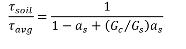
where,
as = area replacement ratio
Gc = shear modulus of the column
Gs = shear modulus of the soil
Substituting n for Gc/Gs in the above expression gives: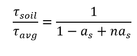
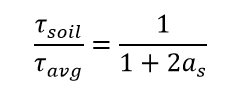
As an example, if a safe value of n is assumed to be 3, then:
and if as = 0.3, then:
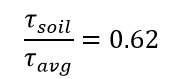
which represents a 38% reduction in the seismic shear stress applied to the soil. A reduction of this magnitude could provide a significant decrease in the liquefaction potential.
The appropriate value of n in any case depends on the relative stiffness of the column and soil, the slenderness ratio of the columns for unconnected column arrangements, the use of grids formed of continuous shear panels instead of isolated columns, and the overall height-to-width and height-to-length ratios of the treated zone, among other factors. As mentioned above, if the columns are arranged in a grid of overlapping continuous panels it would be expected that n would be higher than if isolated columns are used.
The construction methods used for installation of aggregate columns may provide some densification of the in-situ soil. If consistent improvement of the soil can by verified by QA testing, then there will be an increase in the CRR in addition to the decrease in the CSR caused by the load transfer to the stiffer elements, with a corresponding increase in the factor of safety against liquefaction. The increase in the CRR can be determined using the new values of penetration resistance and appropriate liquefaction charts.
The methods presented by Shenthan et al. (2006) and Priebe (1998) can be used to predict the level of improvement due to the installation of stone columns. Shenthan et al. (2006) provides design charts for estimating post-installation (N1)60 values based on stone column area replacement ratio, pre-installation (N1)60 values, and soil permeability. Priebe (1998) presents a simplified method where a reduced CSR applied to the improved soil is found by multiplying the unimproved soil cyclic stress ratio (CSR0) of the soil by a reduction factor. The reduction factor, , is equal to the remaining stress on the soil between columns divided by the average stress over the entire area, and can be determined from the following equations: 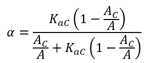
and
![]()
where,
AC = cross sectional area of the column
A = column tributary area
ϕC = column stone friction angle
Shear Strength. If aggregate columns are used for slope stabilization, the strength of the reinforced ground is needed to determine the factor of safety against slope stability failure. Approaches for determining the stability of stone column improved slopes are based on:
- Profile method.
- Composite shear strength method.
- Lumped moment method.
Both composite and discrete element models have been used for aggregate column slope stability analysis. The composite shear strength method, in which averaged values of soil cohesion and friction angle are used, has been used successfully on numerous projects, and has proved to give reliable results. The use of the discrete model approach, in which the columns and native soil are each assigned their own values of cohesion and friction, is becoming more prevalent with commercially available slope stability software.
The composite shear strength method includes the following steps:
- Stress concentrations can be included by using the resulting vertical effective stress acting on the aggregate column and soil failure surface as outlined below:
- First, the vertical effective stress on the aggregate column failure surface is found my multiplying the unit weight of the aggregate by the depth below the ground surface, and then adding this value to the change in stress in the aggregate column due to any surcharge loading considering the stress concentration factor.
- The shear strength of the column can then be determined using equation (36) on p.80 of Barksdale and Bachus (1983a):
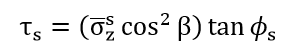 where,τs = shear strength of the aggregate column
σzs = vertical effective stress acting on aggregate column failure surface
β = inclination of the failure surface with respect to the horizontal
ϕs = aggregate internal friction angle - Next, the total vertical stress in the soft soil is found by multiplying the total unit weight of the soil by the depth below the ground surface, and then adding this value to the change in stress in the ground due to any surcharge loading considering the stress concentration factor.
- The undrained shear strength of the soft soil can then be determined using equation (38) on p.82 of Barksdale and Bachus (1983a):
where,
τc = undrained shear strength of the cohesive soil
c = cohesion of cohesive soil (undrained)
σzc = total vertical stress in the cohesive soil acting on the failure surface (considering total weight of soil and reduced surcharge loading)
ϕc = cohesive soil internal friction angle (undrained)
![]()
where,
τ = composite shear strength
as = area replacement ratio, the area of the aggregate columns divided by the total area
4. These composite values are calculated for each row of aggregate columns and then used in a conventional slope stability analysis.