
Technology Fact Sheet Deep Dynamic Compaction
Basic Function:
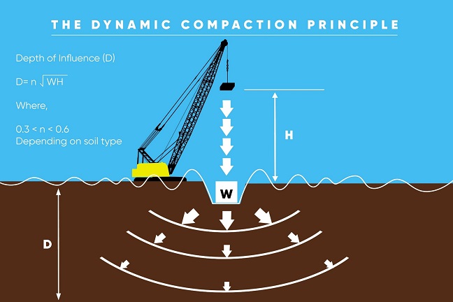
Deep Dynamic Compaction (DDC) densifies marginal materials using high levels of impact energy at the surface.
Applications of Deep Dynamic Compaction:
- Densification of in situ loose or uncontrolled materials to facilitate surface construction of buildings, roadways, embankments, or other structures.
- Compression of Municipal Solid Waste (MSW) materials to gain air space in landfills.
- Improvement of surficial soils in the zone that provides primary lateral resistance to deep foundation elements, improving the lateral capacity of those elements.
Probing of karst sites to evaluate potential soft zones associated with underlying sinkhole features.
General Description:
Deep Dynamic Compaction is the introduction of multiple passes of high energy impacts at ground level by repeatedly dropping tampers (typically steel) of 6 to 30 tons from drop heights of 30 to 100 feet. This high-energy impact creates a shock wave that reduces the void ratio and increases and improves the density of the soil, identifying loose zones and soft spots throughout the process. In doing so, the need for off-site removal of the existing soils for replacement with compacted granular fill or implementation of more costly ground improvement or deep foundation options can be reduced or eliminated.
Geologic Applicability:
- Loose pervious and semi-pervious soils with fines contents less than 15%
- Subsurface conditions including large voids
- Soil improvement to a maximum depth of about 20 to 30 feet
- Not recommended for silty or clayey soils
- Effective in soils above or below the groundwater table (Note: Water table should be 6 feet below grade; fill can be placed above a high groundwater site to achieve this distance.)
Construction Methods:
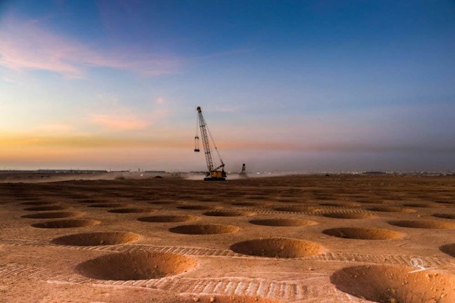
A tamper with a weight of 6 to 30 tons is dropped using a crane from a height of 30 to 100 feet. The tamper is dropped in a systematically controlled pattern. The impacts are spaced at a distance depending on the depth of the compressible layer, the depth to the groundwater, grain size distribution, and improvement objective. Five to 15 blows per grid point are applied. The first phase is the high-energy phase to improve the deeper layers; this generally consists of offsetting primary and secondary passes. This is followed by a low-energy phase to densify the upper layers, typically referred to as an ironing pass. In the low-energy phase, the tamper is only raised 15 to 20 feet. Backfilling of the craters created by the tamper impacts and additional passes may be required.
Additional Information:
Proximity of groundwater or excessive crater depths limit the number of blows at each grid point. In saturated soils with some fines (less than 15% fines), the compaction may create excess pore water pressure that delays the effectiveness of compaction unless the pressure is dissipated. DDC is generally more economical than other technologies for large area ground improvements..
SHRP2 Applications:
- New Embankment and Roadway Construction
- Roadway and Embankment Widening
Example Successful Applications:
- Densification of uncontrolled fill materials – Prudential Center, Newark, New Jersey
- Densification of mine spoil materials – Warehouse site, Olyphant, Pennsylvania
- Densification of MSW materials, warehouse site, Hialeah, Florida
- Study Site – Charleston, SC
Complementary Technologies:
Prefabricated vertical drains (without fill preloading) to dissipate pore water pressures and improve densification of soils with higher fines content (more than 20-30%).
Alternate Technologies:
- Removal and Replacement
- Rapid Impact Compaction
- High Energy Impact Compaction
- Vibrocompaction
- Aggregate Piers
- Blast Densification
- Rigid Inclusions
- Deep Foundation Systems
Advantages:
- Suitable for many types of soils with less than 15% fines
- Low cost for large area of improvement
- Ability to measure improvement
- Simple equipment
- Produces relatively uniform compressibility
Potential Disadvantages:
- Depth of influence can be limited when compared to other densification methods such as vibrocompaction.
- Construction-generated vibrations can be problematic for structures or utilities within close proximity of the improvement zone.
Key References for this technology:
Elias, V., Welsh, J., Warren, J., Lukas, R., Collin, J. G., and Berg, R. R. (2006). “Ground Improvement Methods”- Volume I. Federal Highway Administration Publication No. NHI-06-020.
Lukas, R.G. (1986). “Dynamic Compaction for Highway Construction Volume I: Design and Construction Guidelines.” U.S. Department of Transportation, Federal Highway Admin., Washington, D.C., FHWA/RD-86/133.
Lukas, R.G. (1995). “Dynamic Compaction – Geotechnical Engineering Circular No. 1”, U.S. Department of Transportation, Federal Highway Administration, Washington, D.C., FHWA-SA-95-037.