
Case Study: The Carsington Dam Failure (Derby, UK, 1984)
By Michael Bennett, P.E., M.ASCE (GFT: Audubon, PA)
In 1932, seasoned American civil engineer Joel Justin opened his book Earth Dam Projects by noting:
“Broadly speaking, man learns only by his failures. Hence, it is of prime importance for engineers charged with the design and construction of earth dams to study the failures of the past, for fortunate is the man who can learn from the failures of others rather than from his own” (Justin 1932).
Much of Justin’s manual on the proper design and construction of embankment dams is solidly outdated over 90 years later, to say nothing of his language on how humanity learns. Yet his opening remarks remain as timely as they were the year FDR first ran for president. The study of history of all kinds allows us to learn on the dimes of our forebears, and that is seldom clearer than when one studies geotechnical and dam engineering failures. Indeed, the Association of State Dam Safety Officials (ASDSO) maintains a robust website (https://damsafety.org/dam-failures) devoted to dam failure and incident case studies so modern engineers can learn from their predecessors’ mistakes. The site, to which the author has contributed several entries, represents an invaluable resource to geo-professionals ( on the topic of dam engineering failures.
Of course, not all such failures are created equal. The phrase “dam engineering failure” calls to mind sobering images of water roaring through a breach after heavy rain, frantic evacuations as a wave thunders down a valley, and a long, difficult, and emotional process of cleaning up and rebuilding. It takes nothing away from such heartrending scenes to note that not all dam failures are quite so catastrophic. Plenty result in property damage and destruction, project scheduling setbacks, and bitter and often litigious disputes over responsibility yet are at least free from the angst that accompanies deaths or serious injuries. One such lower-key failure is the UK’s Carsington Dam, which in 1984 underwent a major slope failure just as construction was concluding. It resulted in neither flooding nor fatalities but still led to major technical advances – and badly embarrassed many parties.
Carsington Dam, which was rebuilt following the 1984 slide, lies near the River Derwent and is roughly 10 miles northwest of the city of Derby. (Fans of the legend of Robin Hood may be interested to learn that the real Sherwood Forest sits 25 miles east-northeast of the reservoir.) The structure was first planned in the late 1960s to improve central England’s water supply and was designed in the late 1970s. The dam was planned to be 120 feet tall, 4,020 feet long, and capable of retaining 28,400 acre-feet of water. Construction began in spring 1981 (Kennard and Bromhead 2000, Rocke 1993, Sachpazis 2013, Skempton and Vaughan 1993).
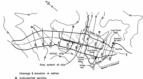
Image 1: Layout of the original Carsington Dam, annotated with the future failure zone.
Source: Skempton (1985).
From the start, the geotechnical design of the original Carsington Dam fell far short of the standard of care. The designers generally followed the typical design of an embankment dam – clay core, inner and outer shoulders, drainage features, and so forth – and incorporated some standard geotechnical features into their work, such as grout curtains and uplift wells for seepage control. However, the team insufficiently considered several other key geotechnical factors. The site subsurface investigation found roughly 6 feet of highly plastic yellow clay beneath the topsoil, but the designers never specified that this potentially problematic material needed to be removed from the dam’s footprint. Nor did they note that the yellow clay contained shear surfaces from historical solifluction (landslides induced by freeze-thaw cycles) at the site. The team conducted only minimal lab testing before choosing material parameters that pushed, and in some cases overstepped, the limits of appropriate conservatism. This was especially concerning since the designers included an unconventional toe, dubbed a “boot,” in the upstream side of the dam’s clay core. Such a boot presents clear risks for sliding within a dam, but the team did not rigorously evaluate probable slip surfaces through it. In fact, evidence suggests that critical slip surfaces within the dam were never systematically assessed. Neither, apparently, was the potential for progressive shear failure within the structure (Kennard and Bromhead 2000, Rocke 1993, Sachpazis 2013, Skempton and Vaughan 1993).
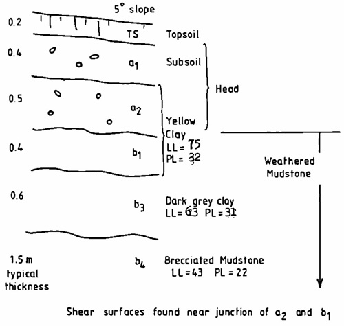
Image 2: Stratigraphy of post-failure test pit excavated at the Carsington Dam site.
Source: Skempton (1985).
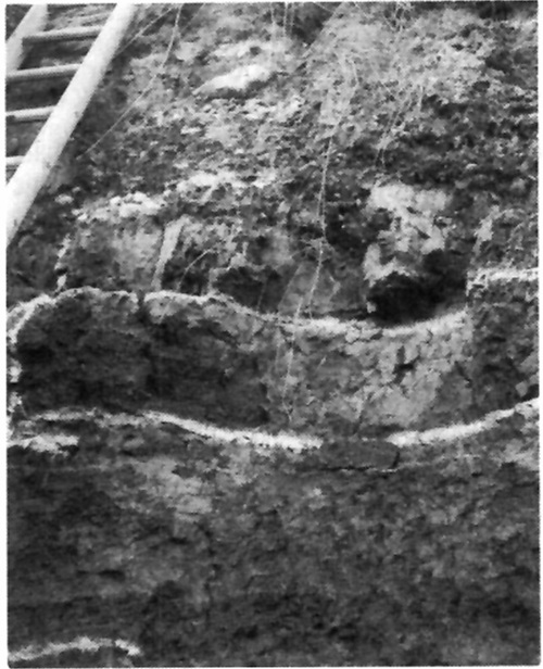
Image 3: Suspected solifluction surface in a post-failure test pit.
Source: Rowe (1991).
The woes at Carsington Dam intensified as fill placement for the embankment got underway in summer 1982. The designers had called for the dam’s core to be built of yellow clay excavated from on-site borrow pits, notwithstanding its solifluction shears. The team also failed to account for the elevated pyrite content of the mudstone clay used for the dam’s upstream shell when choosing to use limestone riprap on, and drainage blankets within, the embankment. This created the potential for sulfuric acid leaching from the mudstone clay to react disastrously with the calcium carbonate in the limestone, potentially producing excessive build-ups of carbon dioxide. Tragically, this possibility came to pass; during construction, four workers died of asphyxiation while inspecting a drainage tunnel in which gases from pyrite drainage-limestone reactions had built up (Baldermann et al. 2024, Kennard and Bromhead 2000, Penman et al. 1995, Skempton 1985, Skempton and Vaughan 1993).
Image 4: Cross-section of the original Carsington Dam. Source: Skempton and Vaughan (1993).
While the designers’ choices began having detrimental impacts on Carsington Dam well before it approached completion, several of the contractor’s construction decisions exacerbated these problems. For example, the contractor placed and compacted the core and boot clay as much as 8% wet of its optimum moisture content, leading to high pore pressures and low shear strength within the already problematic material. At another point, the contractor built a 20-foot-high toe berm extending about 785 feet along the structure’s upstream face. This choice allowed for quicker embankment construction but also reduced the already inadequate time available for the core’s oversaturated clay to consolidate. Furthermore, the contractor’s compaction machinery created numerous ruts within the yellow clay, each representing a potential new slip surface. Later analyses determined that these ruts most likely played only a minor role, if any, in the dam’s failure, but their presence reflected the cursory consideration with which all too many decisions on the project were made (Kennard and Bromhead 2000, Penman et al. 1995, Rocke 1993, Skempton 1985, Skempton and Vaughan 1993)
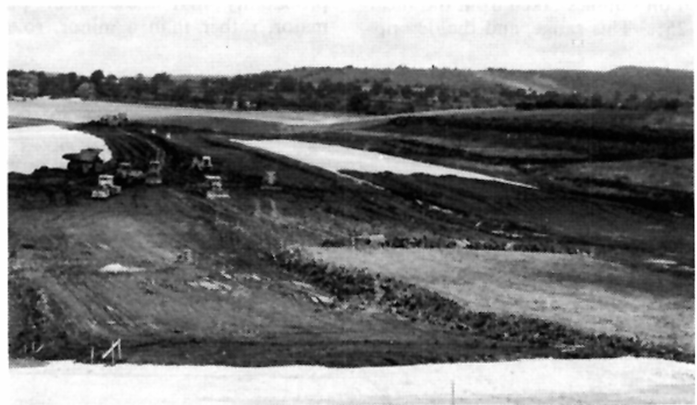
Image 5: Embankment construction progresses at the original Carsington Dam.
Source: Rowe (1991).
Despite these shortfalls, the contractor was generally more on top of the issues at the dam than the design team and harbored more concerns about the project from its outset. As work progressed, the contractor became increasingly doubtful of the design’s success, especially as instrumentation installed in the dam at the designer’s behest began indicating an incipient slope movement along its upstream face. By mid-1983, the contractor had seen enough and engaged outside engineering consultants to evaluate its concerns. The consultants reported back that fall, validating these concerns and calling attention to the designer’s insufficiently conservative parameters, improper assessment of potential slip surfaces through the boot, and worrisome instrumentation data. The contractor immediately forwarded the report to the design team and attempted to meet them to discuss both the findings and potential design modifications. Yet the designers never acknowledged these outreaches and construction continued apace (Kennard and Bromhead 2000, Penman et al. 1995, Skempton and Vaughan 1993).
The problems remained, though, and work at Carsington Dam soon came to a juddering halt. The earliest sign of imminent trouble came in late May 1984 when a section of the dam’s upstream face near the eventual slide location moved about 4 inches laterally in just a week. The first weekend of June likely worsened the nascent issues, as approximately 1.6 inches of rain fell. When the contractor’s crews returned to the jobsite on Monday, June 4th, they discovered that a head scarp crack up to 2 inches wide had formed along a 395-foot stretch of the dam’s upstream face. Moreover, its toe in this region now exhibited as much as 3 to 4 inches of lateral displacement. The crews began an emergency expansion of the upstream toe berm right away, hoping to arrest the slide, but the problem quickly worsened and their valiant efforts proved fruitless. By Monday evening, the crack was as much as 5 inches wide. The next morning, it had grown up to 14 inches wide and was getting longer. By Tuesday afternoon, as the crews continued toiling on the berm, the crack was widening as much as 6 inches per hour; by that evening, it extended along 1,540 feet of the dam, and portions of the upstream toe exhibited up to 8 feet of lateral displacement. Even larger movements occurred overnight from Tuesday to Wednesday. When the slope finally stopped sliding on Thursday, June 7th, the failure had a lateral extent of roughly 1,625 feet. The dam’s upstream slope had undergone up to 43 feet of lateral displacement, and its crest had slid downward as much as 33 feet (Rowe 1991, Skempton and Coats 1985, Skempton and Vaughan 1993).
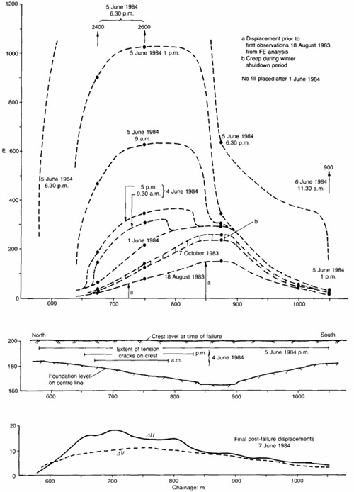
Image 6: Map of lateral displacements along the upstream toe of the original Carsington Dam early in the slope failure.
Source: Skempton and Vaughan (1993).
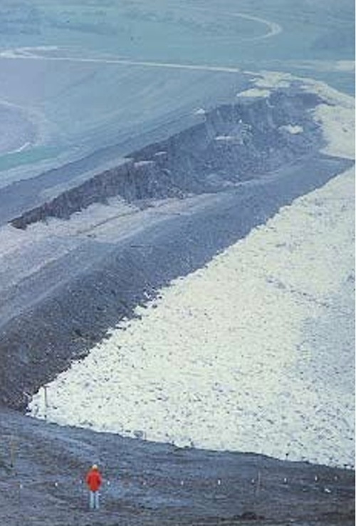
Image 7: Aftermath of the slope failure at the original Carsington Dam.
Source: Rofe et al. (1996).
Since Carsington Dam was still under construction, its failure fortunately led to neither flooding nor human casualties. Still, the subsequent investigation and rebuilding process was – like any other – long and expensive. The post-slide geotechnical forensic investigation and failure analyses constituted a noteworthy achievement in dam engineering. The client, designer, contractor, and forensic engineers were all eager to get to the root of what had happened, and the investigation was therefore a surprisingly cooperative effort. “A remarkable degree of unanimity existed among the [investigative] committee members,” one geotechnical engineer involved in the effort noted. The forensic site work included a thorough regimen of sampling and laboratory testing, along with an extensive battery of CPT probes. (The hazards overlooked in design were reaffirmed when some test pits had to be ventilated before sampling due to excessive carbon dioxide from the pyrite drainage-limestone reactions.) Meanwhile, the analyses used finite element models to successfully establish that progressive failure had occurred. This represented a major advance for the geotechnical profession, since limit equilibrium models still predominated in failure analyses of dams 40 years ago (Potts et al. 1990, Rocke 1993).
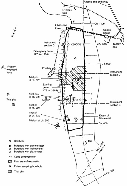
Image 8: Map of sampling for the forensic investigation at Carsington Dam.
Source: Rocke (1993).
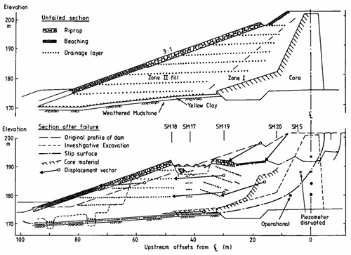
Image 9: Cross-sections of the original Carsington Dam before and after the slope failure.
Source: Skempton (1985).
Ultimately, the forensic engineers concluded that the Carsington Dam slide stemmed primarily from a combination of the factors hitherto described. The slip surface had extended through the core boot and the thin stratum of yellow clay left in place beneath the dam. Since this clay was brittle, a geotechnical phenomenon not yet widely recognized in 1984, the core had undergone non-uniform strain and had failed progressively. Thus, the exclusive use of peak or even fully softened shear strength parameters in design without considering residual strength had been erroneous. Eventually, the solifluction surfaces in the yellow clay, both in the core and beneath the dam, and progressive failure had lowered the factor of safety for slope stability at the initial point of failure to 1, resulting in the slide. As the failure played out, lateral load transfer shifted forces from the failed portion of the dam onto adjacent portions, reducing their already perilously low FS values to 1 and propagating the failure outward. The FEM work also showed that the contractor’s construction of a buttress berm along the dam’s upstream toe had increased the FS of the tenuously stable slope far less than LEM-based calculations had predicted (Kennard and Bromhead 2000, Rocke 1993, Skempton and Vaughan 1993, Vaughan 1991).
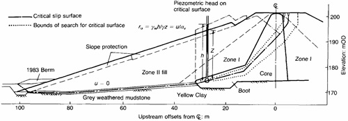
Image 10: Cross-section of initial surface of slope failure within the original Carsington Dam.
Source: Skempton and Vaughan (1993).
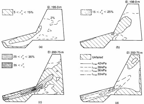
Image 11: Cross-sections of strain (a-c) and shear stress (d) within the clay core and boot of the original Carsington Dam showing onset of progressive failure.
Source: Potts et al. (1990).
The civil engineers who analyzed the Carsington Dam slide emphasized that the dam’s reconstruction, if undertaken, would need to incorporate better choices of design parameters, more consideration of the possibility of progressive failure and probable slip surfaces, and – perhaps most importantly – receptiveness by the design team to concerns from the contractor and/or outside consulting engineers. The disaster made clear the importance of recognizing the brittle nature of some clays, considering progressive failure in dam design, and, as a corollary, using FEM in these designs to assess slope stability. The failure prompted years of vigorous and productive discussion in the British dam engineering community about the nature and proper modeling of progressive failure in clays. Esteemed geotechnical practitioner A.D.M. Penman channeled Joel Justin’s admonition of 60 years earlier when he wrote, “We must always be grateful for the opportunity to analyze failure – without failure we know less about the actual mechanisms of failure” (Penman et al. 1995).
Design of the new Carsington Dam began almost as soon as the forensic investigators released their findings. The new design team included several features in the revamped dam to ensure it avoided its predecessor’s fate. The new, more geotechnically rigorous design utilized more conservative material parameters that reflected an improved understanding of progressive failures. The designers eliminated the core boot and limestone drainage blankets, instead opting for a downstream filter drain. They significantly reduced the embankment’s slopes from 3:1 (H:V) to 3.5:1 along its upstream face and from 2.5:1 to 3:1 along its downstream face and added berm-like steps along both faces for additional stability. The designers used FEM analyses to confirm the new design’s robustness. During construction, the designers and contractors drew upon an extensive instrumentation program to check that observed and predicted soil behavior were congruent, as they proved to be. They also implemented strict protocols to prevent machine-induced rutting shear surfaces in the clay core. The job was further complicated by the need to remove over 2.6 million CY of failed material from the original dam during construction of the new dam (Chalmers et al. 1993, Macdonald et al. 1993, Rocke 1993, Sachpazis 2013).
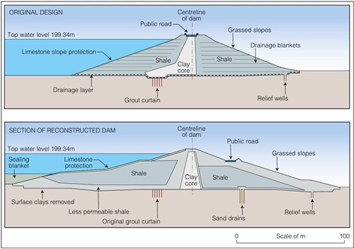
Image 12: Comparison of cross-sections of the original and rebuilt Carsington Dams showing refinements to the new design.
Source: Rofe et al. (1996).
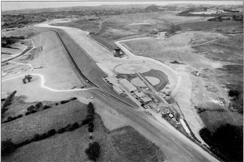
Image 13: Construction of the rebuilt Carsington Dam nears completion.
Source: Macdonald et al. (1993).
Despite the project’s many constraints, the contractors completed the new Carsington Dam in October 1991, 12 months ahead of schedule. It has performed satisfactorily since then under the watchful eye of its owners, Severn Trent Water, and their Chartered Engineers (the UK equivalent of US Professional Engineers). The Carsington Reservoir is now a popular recreation spot for walkers and runners, water sports enthusiasts, and nature watchers and it represents an exceptionally happy ending to a dam failure saga. Still, geo-professionals and dam engineers must be mindful that the success story of the rebuilt Carsington Dam resulted directly from the failure story of its forerunner. Four decades have passed since the original Carsington Dam failed, but it remains a valuable teaching tool. The tranquil scene of Carsington Reservoir today is, in its own way, a stern reminder to civil engineers the world over that not all that ends well necessarily is well – and that learning on our forebears’ dimes is far more affordable than learning on our own (Macdonald et al. 1993).
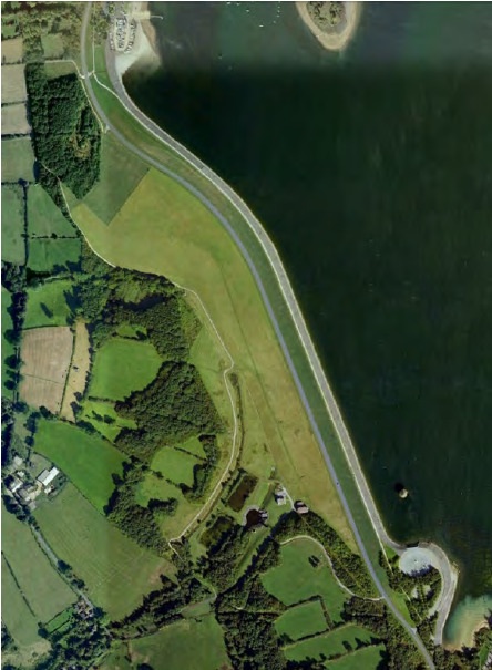
Image 14: Overhead view of the rebuilt Carsington Dam as it currently stands.
Source: Sachpazis (2013).
Acknowledgments
Sebastian Lobo-Guerrero, Ph.D., P.E., BC.GE, F.ASCE (A.G.E.S., Inc.: Canonsburg, PA), the author’s former colleague, reviewed the entry’s geotechnical content. Prof. Alba Yerro-Colom (Virginia Tech: Blacksburg, VA) introduced the author and his classmates to the Carsington Dam failure in her spring 2019 course on Numerical Methods in Geotechnics. The author has adapted this entry from his forthcoming contribution on Carsington Dam to ASDSO’s Dam Failures and Incidents website.
References
Baldermann, A., R. Boch, V. Reinprecht, and C. Baldermann. 2024. “Mechanism of carbon monoxide (CO) generation and potential human health hazard during mechanized tunnel driving in organic-rich rocks: Field and laboratory study.” Sustainability, 16, 8107; 17 pp. https://www.mdpi.com/2071-1050/16/18/8107
Chalmers, R.W., P.R. Vaughan, and D.J. Coats. 1993. “Reconstructed Carsington Dam: Design and performance.” Proc. Inst. Civ. Eng. Water Marit. Eng., 101 (1), 1-16. https://www.icevirtuallibrary.com/doi/10.1680/iwtme.1993.22977
Justin, J.D. 1932. Earth dam projects. New York, NY: John Wiley and Sons.
Kennard, M.F., and E.N. Bromhead. 2000. “Carsington Dam – The near-miss which became a bulls-eye.” Proc. 2nd Cong. Forensic Eng., 102-111. https://doi.org/10.1061/40482(280)12
Macdonald, A., G.M. Dawson, and D.C. Coleshill. 1993. “Reconstructed Carsington Dam: Construction.” Proc. Inst. Civ. Eng. Water Marit. Eng., 101 (1), 17-30. https://www.icevirtuallibrary.com/doi/abs/10.1680/iwtme.1993.22980
Penman, A.D.M., D.W. Cox, M.F. Kennard, E.N. Bromhead, J.A. Dunster, P.W. Rowe, E.H. Taylor, A.W. Skempton, and P.R. Vaughan. 1995. “Discussion: The failure of Carsington Dam.” Géotechnique, 45 (4), 719-739. https://www.icevirtuallibrary.com/doi/abs/10.1680/geot.1995.45.4.719
Potts, D.M., G.T. Dounias, and P.R. Vaughan. 1990. “Finite element analysis of progressive failure of Carsington embankment.” Géotechnique, 40 (1), 79-101. https://www.icevirtuallibrary.com/doi/10.1680/geot.1990.40.1.79
Rocke, G. 1993. “Investigation of the failure of Carsington Dam.” Géotechnique, 43 (1), 175-180. https://www.icevirtuallibrary.com/doi/abs/10.1680/geot.1993.43.1.175
Rofe, B.H., D.J. Knight, J.A. Dunster, D.J. Coats, G.P. Sims, G. Rocke, D.W. Cox, K. Banyard, R.E. Coxon, and T.A. Johnston. 1996. “Discussion: Carsington Reservoir – Reconstruction of the dam.” Proc. Inst. Civ. Eng.: Civ. Eng., 114 (2), 92-96. https://www.icevirtuallibrary.com/doi/abs/10.1680/icien.1996.28258
Rowe, P.W. 1991. “A reassessment of the causes of the Carsington embankment failure.” Géotechnique, 41 (3), 395-421. https://www.icevirtuallibrary.com/doi/10.1680/geot.1991.41.3.395
Sachpazis, C.I. 2013. “Detailed slope stability analysis and assessment of the original Carsington Earth Embankment Dam failure in the UK.” Electron. J. Geotech. Eng., 18 (Z), 6021-6060. https://www.researchgate.net/profile/Costas-Sachpazis/publication/259715072_Detailed_Slope_Stability_Analysis_and_Assessment_of_the_Original_Carsington_Earth_Embankment_Dam_Failure_in_the_UK/links/0a85e52d6ffdeaf61b000000/Detailed-Slope-Stability-Analysis-and-Assessment-of-the-Original-Carsington-Earth-Embankment-Dam-Failure-in-the-UK.pdf
Skempton, A.W. 1985. “Geotechnical aspects of the Carsington Dam failure.” Proc. 11th Int. Conf. Soil Mech. Found. Eng., 2581-2591.https://www.issmge.org/publications/publication/geotechnical-aspects-of-the-carsington-dam-failure
Skempton, A.W., and D. J. Coats. 1985. “Carsington Dam failure.” Proc. Symp. Fail. Earthworks, 203-220.https://www.icevirtuallibrary.com/doi/full/10.1680/fie.02432.0016
Skempton, A.W., and P.R. Vaughan. 1993. “The failure of Carsington Dam.” Géotechnique, 43 (1), 151-173. https://www.icevirtuallibrary.com/doi/abs/10.1680/geot.1993.43.1.151
Vaughan, P.R. 1991. “Stability analysis of deep slides in brittle soil – lessons from Carsington.” Proc. Int. Conf. Slope Stab., 1-11. https://www.icevirtuallibrary.com/doi/abs/10.1680/ssedaa.16606.0001